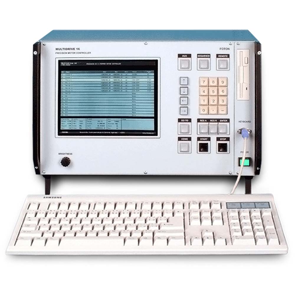
Multidrive 16 is a universal system for controlling and driving DC or stepper motors as well as rotary or linear actuators. The device has a modular, modern design and is capable of controlling up to 16 motors or actuators.
Originally, the device was developed to control precision actuators at optical positioning systems used mainly by the academic and R&D sector. However, due to its versatility and the range of motors it can control, the device is also suitable for demanding industrial applications.
The device consists of the system unit and individual output modules.
System Unit
The core of the system unit is the Main system board, which houses the following functional blocks: CPU MainBoard based on an industrial PC, Input/output board providing for communication between the CPU MainBoard and other circuits, particularly output modules, LCD control and power circuits, and circuits that galvanically separate trigger signals from the external communication signals.
The CPU unit directly controls an LCD display, an external monitor (standard PC), 3.5″ floppy drive, external and internal keyboard and a speaker. The system unit also includes a connection board with 16 free slots for output modules.
The device is power supplied from a switch mode power unit.
The device can be operated either as a stand-alone system, in which case it is controlled through an internal 16-key keyboard or an external standard PC keyboard, or remotely over a serial RS-232 line. Pre-programmed sequences of motor motions can be also triggered by external TTL or optical impulses.
The housing of the system unit is made of a high-quality metallic case of the standard 19″ dimension. It can be either fast mounted in 19″ racks or operated in free table top position.
Output Modules
Output modules generate power and control signals for a specific type of motor (actuator). They are designed and optimised to ensure accurate homing of the motor in a defined position or to ensure an accurate linear movement by a defined length allowing at the same time to set up the velocity profile. As a standard, DC MOTOR and STEPPER MOTOR output modules are supplied.
Velocity profile generator generates temporally dependent control signals corresponding to the required velocity of the motor. The velocity profile is defined by 5 parameters (acceleration, deceleration, max and min velocity, stopping distance). The signals from the velocity profile generator are used to generate control voltage (for DC motors) or clock pulses (for the stepper motor) that consequently control the output driver. The output driver has an in-built PWM output current stabilisation. The position of the motor is monitored by the pulse counter with the pulses coming either from the encoder (if the actuator includes an encoder) or from the pulse generator (in the case of stepper motors without an encoder).
The system is regulated by a feedback system.
Output modules also contain circuits for checking of the stop position status or for processing home position identification signals (in the case of some actuators).
Compatible Motors and Actuators
The following list shows some compatible motors or actuators. For the latest information, please contact our company or click here.
Device Operation and SW
Operating of the device is very intuitive and simple. The device can be easily configured. By selecting a motor from the database, which is a standard part of the basic software package, optimum operational parameters can be set up. For more convenience, individual channels of the device can be given symbolic names.
All settings, configuration, etc. are automatically saved in the device. The data can be also saved to (or loaded from) a 3.5″ floppy disc or they can be transferred to an external computer over a serial line.
The device also includes basic SW for controlling the serial communication with the device. The system and application SW is under continuous development. For the latest information click here.
Parameters
|
No of output channels |
8, 16 or per the customer’s specifications |
|
Output modules |
DC MOTOR/STEPPER MOTOR |
|
Standard indicated resolution |
0.1 microns/0.001 ° |
|
Travel range |
depending on the motor type |
|
Single step |
depending on the motor type |
|
Limit status check |
yes |
|
Home & Index signals |
yes |
|
Output voltage (DC) |
0 to ±12 V |
|
Output voltage (STEPPER) |
30 V (PWM) |
|
Internal keyboard |
16 keys |
|
External keyboard |
standard PC keyboard |
|
Display |
VGA mono/colour |
|
External monitor |
standard PC (15-way D-sub) |
|
Floppy drive |
standard 3,5″ |
|
No of motions per sequence |
up to 10 |
|
Sequence triggering |
manual, external (serial line), trigger signal |
|
Trigger input |
TTL (BNC, 50 Ω) or opto (FC/PC) |
|
Trigger output |
TTL (BNC, 50 Ω) or opto (FC/PC, 62.5) |
|
Communication |
RS-232 (TxD, RxD, GND), D-sub 9 |
|
Baud rate |
9600 Bd |
|
Communication details |
8 bit, 1 stop bit, no parity |
|
Power |
230 VAC, 50/60 Hz, 40 VA |
|
Dimensions |
19″ × 6U × 280 mm (483 × 264 × 280 mm) |
| Weight | 12 kg |
List of Compatible Motors and Actuators
(Rev. March 2003)
|
Newport Corporation |
CMA-12PP, CMA-25PP, CMA-12CCCL, |
|
Thorlabs Inc. |
Z606, Z612, Z612B, Z625B |
|
Spectra-Physics Inc. (Oriel) |
Encoder Mikes |
Latest SW Information
(Rev. 22. 4. 2003)
1. System SW
(Ver. 2003 – 1.a)
|
ID |
Command Name |
Keyboard Code |
Description |
Notes |
|
1 |
ArrowUp |
<↑> |
Channel selection and cursor location in editor modes |
A, B, C |
|
2 |
ArrowDown |
<↓> |
Channel selection and cursor location in editor modes |
A, B, C |
|
3 |
ArrowLeft |
<←> |
Single step to outer dimension, cursor location in editor modes |
A, B, C |
|
4 |
ArrowRight |
<→> |
Single step to inner dimension, cursor location in editor modes |
A, B, C |
|
5 |
Goto |
<CTRL> + <G> |
Input of destination position (referred ro Relative Position). Input numbers are modified with respect to motor/actuator type. |
A, B, C |
|
6 |
RunTo |
<CTRL> + <F9> |
Run to the position defined by Goto command |
A, B, C |
|
7 |
Stop |
<space bar> |
Stop of currently running motor or actuator, Emergency stop |
A, B, C |
|
8 |
Absolute_Counter_Reset |
<CTRL> + <A> |
Reset of Absolute Counter |
A, B, C |
|
9 |
Relative_Counter_Reset |
<CTRL> + <R> |
Reset of Relative Counter |
A, B, C |
|
10 |
Homing |
<Home> |
Run to the “Home” position |
A, B, C |
|
11 |
Name_Editor |
<CTRL> + <N> |
Name editor – input of channel identification names |
B, C |
|
12 |
Motor_Editor |
<CTRL> + <M> |
Motor editor – selection of connected motors or actuators |
B, C |
|
13 |
Sequence_Editor |
<CTRL> + <S> |
Sequence editor – definition of “Sequence” (1–10 motor runnings) |
B, C |
|
14 |
Start_Sequence |
<CTRL> + <T> |
Performance of “Sequence” |
A, B, C |
|
15 |
Remote_Control |
<F6> |
Remote Control Mode ON/OFF |
A, B |
|
16 |
Save_Config_Ext |
<CTRL> + <C> |
Saves configuration files on floppy disc |
B |
|
17 |
Load_Config_Ext |
<CTRL> + <L> |
Retrieves configuration files from floppy disc |
B |
|
18 |
Save_Config_Serial_1 |
X |
Writes 1st configuration file on serial line |
B, C |
|
19 |
Save_Config_Serial_2 |
X |
Writes 2nd configuration file on serial line |
B, C |
|
20 |
Save_Config_Serial_3 |
X |
Writes 3rd configuration file on serial line |
B, C |
|
21 |
Load_Config_Serial_1 |
X |
Reads 1st configuration file from serial line |
B, C |
|
22 |
Load_Config_Serial_2 |
X |
Reads 2nd configuration file from serial line |
B, C |
|
23 |
Load_Config_Serial_3 |
X |
Reads 3rd configuration file from serial line |
B, C |
|
24 |
Load_Moto_DB_Ext |
X |
Reads motor database file from floppy disc |
B |
|
25 |
Load_Moto_DB_Serial |
X |
Reads motor database file from serial line |
B, C |
|
26 |
Save_Positions_Ext |
X |
Saves current positions on floppy disc |
B |
|
27 |
Load_Positions_Ext |
X |
Retrieves current positions from floppy disc |
B |
|
28 |
Save_Positions_Serial |
X |
Writes current positions on serial line |
B, C |
|
29 |
Load_Positions_Serial |
X |
Reads current positions from serial line |
B, C |
|
30 |
S_Set_Channel |
|
Activates a new channel |
C |
|
31 |
S_Read_Channel |
|
Reads active channel |
C |
|
32 |
S_Read_Pos_Abs |
|
Reads Absolute Counter Position of active channel |
C |
|
33 |
S_Read_Pos_Rel |
|
Reads Relative Counter Position of active channel |
C |
|
34 |
S_Read_Pos_Abs_All |
|
Reads Absolute Counter Positions of all channels |
C |
|
35 |
S_Read_Pos_Rel_All |
|
Reads Relative Counter Positions of all channels |
C |
|
36 |
S_Read_Limit_Status |
|
Reads status of limits of active channel |
C |
|
37 |
S_Read_Limits_All |
|
Read status of limits of all channels |
C |
|
38 |
S_Counter_Preset_Abs |
|
Presets Absolute Counter Position of active channel |
C |
|
39 |
S_Counter_Preset_Rel |
|
Presets Relative Counter Position of active channel |
C |
Notes
A … internal keyboard command
B … external keyboard command
C … serial line command
D … TTL I/O command
E … optical I/O command
2. m16t.exe
Simple terminal for serial control (DOS)
3. Multidrive16_Terminal (*)
Terminal for serial control (Windows)
4. M16_LIBC (*)
C, C++ drivers and libraries
5. M16_DLL (*)
DLL for Windows
Recenze
Zatím zde nejsou žádné recenze.